Maximum Volume:
In the following tasks, you will determine the maximum volume of several containers. You will first construct the 3-dimensional container, and then you will determine what must be removed in order to maximize its volume.
Keep in mind some of the following questions.
1) Does the shape of the original material alter your findings?
2) Why is it important to be able to determine what the maximum volume would be? Who would be interested in knowing what you find?
3) Can you construct other objects and determine the maximum volume?
Task 1:
Box Problem
What size square should be cut out of the corner in order to maximize the volume of the box?
This problem can be approached many ways. Most start with simulations but this may take too long to cut out several different sizes of boxes. Sketchpad can enable us to create one model and then, since it is dynamic we can manipulate the original givens.
1)
![]() We will need to start by constructing a rectangle. You may also choose to construct a
square. Begin by creating a line
segment in the middle of the sketch.
We will need to start by constructing a rectangle. You may also choose to construct a
square. Begin by creating a line
segment in the middle of the sketch.
2)

 Using the arrow tool, highlight both
endpoints of the segment and the middle of the segment at the same time. Under
the Construct menu select Perpendicular Lines. (For a square, you can rotate the
initial line segment 90° and -90° to form 3 of the congruent sides, then
connect them for the
Using the arrow tool, highlight both
endpoints of the segment and the middle of the segment at the same time. Under
the Construct menu select Perpendicular Lines. (For a square, you can rotate the
initial line segment 90° and -90° to form 3 of the congruent sides, then
connect them for the
 fourth side, then skip to step 9).
3) Place a point on one of the newly created perpendicular lines with the point tool.
4)
![]() Highlight the point you just created and one
of the perpendicular lines at the same time. Under the Construct
menu select Perpendicular Lines.
Highlight the point you just created and one
of the perpendicular lines at the same time. Under the Construct
menu select Perpendicular Lines.
5) Using the arrow tool click on the precise intersection point of the other perpendicular line and the new line.
6)
 Next, highlight all of the lines with the
selection tool (It is not necessary to select the segment at the bottom only
the lines on the left, right, and top side of the rectangle need to be
highlighted. Also, make sure that none of the points are selected). Under the Display Menu
select Hide Lines.
Next, highlight all of the lines with the
selection tool (It is not necessary to select the segment at the bottom only
the lines on the left, right, and top side of the rectangle need to be
highlighted. Also, make sure that none of the points are selected). Under the Display Menu
select Hide Lines.
7) Using the segment tool, reconnect all of the points
8)
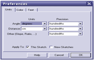
Under the Edit menu
select Preferences… Make
sure the Distance Units are set to cm (Although our model suggests
inches, centimeters may be more manageable and our results won’t change if we
let our scale be 1cm represents 1 inch using a computer screen display of 800x600 or greater
resolution. The scale will need to
be altered if this screen resolution is not possible)
9)
 Next,
we will set the size of the square to be cut out by creating a quick slider
tool that will represent the length of a side of a square. A small line
segment beneath the rectangle would suffice but will make it impossible to
later show the algebraic connections.
Start by creating a ray just below the rectangle.
(Remember to access the ray tool you will need to click and hold down on the
line button.)
Next,
we will set the size of the square to be cut out by creating a quick slider
tool that will represent the length of a side of a square. A small line
segment beneath the rectangle would suffice but will make it impossible to
later show the algebraic connections.
Start by creating a ray just below the rectangle.
(Remember to access the ray tool you will need to click and hold down on the
line button.)

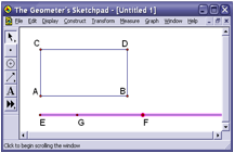 10) Using the point tool put a new point,
labeled point G, on the ray shown in the diagram at the right. Using the arrow tool, select the ray and
point F as shown. Then, under the Display menu select Hide
Objects. This should leave two points directly below the rectangle.
10) Using the point tool put a new point,
labeled point G, on the ray shown in the diagram at the right. Using the arrow tool, select the ray and
point F as shown. Then, under the Display menu select Hide
Objects. This should leave two points directly below the rectangle.
11) Switch back to
the segment tool and connect the two points at the bottom with the segment
tool. Drag the point G close to point E so that only a small segment is left.
(Make sure the segment is small enough that four squares with a side of length ![]() could be cut out of each corner without overlap.)
could be cut out of each corner without overlap.)
12) 
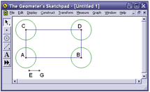 Highlight one of the vertices of the
rectangle and the segment
Highlight one of the vertices of the
rectangle and the segment ![]() at the same
time. Under the Construct menu select Circle by Center and
Radius.
at the same
time. Under the Construct menu select Circle by Center and
Radius.
13) Highlight a different vertex and the segment and again under the Construct menu select Circle by Center and Radius. Repeat this process until all four vertices have circle. As shown at the right.
14) Using the arrow tool, click precisely on the intersection of the rectangle and each of the four circles to create intersection points.
15)  Highlight all four circles at the same time
and then select Hide Circles under the Display
menu.
Highlight all four circles at the same time
and then select Hide Circles under the Display
menu.
16) Create segments
between each of the newly  constructed intersection points as shown in
the picture at the right. Then,
highlight the lines and change the Line Width under the Display menu at the top
to “dashed”.
constructed intersection points as shown in
the picture at the right. Then,
highlight the lines and change the Line Width under the Display menu at the top
to “dashed”.
17) Using the arrow tool, click precisely on each of the intersections of each of the dashed lines to create a point at each of the intersections. Using the label tool, label the rest of the points on the sketch. If you would like to re-label a point to a different letter, simply double click with the label tool on the letter itself and change to the desired letter.
18)
Next, we will need to take some measurements for height, width
and length. After a little thought, we would all agree that
![]() would be the
length of the box,
would be the
length of the box,![]() would be the
width, and
would be the
width, and ![]() would be the
height. To measure these lengths highlight the points P and Q at the same time
and select Distance under the Measurement Menu. Do the same for
the other lengths.
would be the
height. To measure these lengths highlight the points P and Q at the same time
and select Distance under the Measurement Menu. Do the same for
the other lengths.
19)  We should probably also measure the length of
our paper so that we may set it to the proper scale. Measure the length of
We should probably also measure the length of
our paper so that we may set it to the proper scale. Measure the length of ![]() and
and ![]() (8.5 x 11) for
now; it may work out to leave the dimensions a bit smaller.
(8.5 x 11) for
now; it may work out to leave the dimensions a bit smaller.
20) We can even go as far to rename the measurements to length of the box, height of the box, width of the box, and so on. By double clicking on the measurements with the label tool and change the label.
21)  To calculate the volume of the box we will
need to multiply
To calculate the volume of the box we will
need to multiply![]() . To do this, select “Calculate” under the Measure menu. This
will bring up the calculator tool. It may be necessary to reposition the
calculator so that we can see the measurements on the sketch. Click and hold
down on the title bar of the calculator and drag it to the desired position.
Then, simply single click on the actual “length of box" measurement
in the sketch, push the * button on the calculator, single
click on the "width of box" measurement, push the * button
on the calculator, single click on the "height of box"
measurement, and push the O.K. button. We should now have a measurement
for volume
. To do this, select “Calculate” under the Measure menu. This
will bring up the calculator tool. It may be necessary to reposition the
calculator so that we can see the measurements on the sketch. Click and hold
down on the title bar of the calculator and drag it to the desired position.
Then, simply single click on the actual “length of box" measurement
in the sketch, push the * button on the calculator, single
click on the "width of box" measurement, push the * button
on the calculator, single click on the "height of box"
measurement, and push the O.K. button. We should now have a measurement
for volume
22) With a little
adjusting, we should be able to attain the appropriate scaled rectangular piece
of 8.5 x 11 cardboard. Then, we can actually dynamically change the size of the
square we cut out (by changing the size of ![]() ) and see in real time the effect on the volume.
) and see in real time the effect on the volume.
23) For a little
further depth, we can even plot the volume of the box as a function of the size
of the square. To do this, we will need to highlight the measurement of ![]() , (x), and then the measurement of Volume (y) in that order.
(Remember the length of
, (x), and then the measurement of Volume (y) in that order.
(Remember the length of ![]() has been changed
to the "height of box").
Next, select Plot as (x, y) under the Graph
menu. This should bring up an x
and y-axes as well as a newly plotted point. It may be necessary to adjust the
graph by moving the origin and or the unit point to change the scale of the
graph in order to see the point.
It may also help to Hide Grid under the Graph menu. Highlight this newly
plotted point and the point G. Finally; select Locus under the Construct
Menu.
has been changed
to the "height of box").
Next, select Plot as (x, y) under the Graph
menu. This should bring up an x
and y-axes as well as a newly plotted point. It may be necessary to adjust the
graph by moving the origin and or the unit point to change the scale of the
graph in order to see the point.
It may also help to Hide Grid under the Graph menu. Highlight this newly
plotted point and the point G. Finally; select Locus under the Construct
Menu.
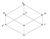
24) To construct the
three dimensional box, first draw a vertical segment longer than the height of
the box. Then select the endpoint
of the segment then![]() , then from the Construct
menu, select circle by center and radius. Then with the point tool, create
the point of intersection of the circle and segment. Then construct and segment from the new point and the
original endpoint. Hide the first
segment.
, then from the Construct
menu, select circle by center and radius. Then with the point tool, create
the point of intersection of the circle and segment. Then construct and segment from the new point and the
original endpoint. Hide the first
segment.
25) Select the original point X and the length of the side of the box, again from the Construct menu, select circle by center and radius. Then construct a point G on the circle and move to an appropriate place on the circle to begin constructing the front of the box.
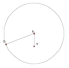
26) Construct the segment from the original point X to the point on the circle then you can hide the circle. Translate the segment you just formed by the length of the vertical segment: Select the point X then the point Y and under the Transform menu, select mark vector. Then select the segment GX and under the Transform menu, select Translate, by marked vector. Then double click on XY, then select all of the segments and points and under the Transform menu, select Reflect.
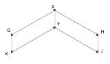
27) Select point G, then the length of the side of the box, then from the Construct menu, select circle by center and radius. Repeat the process at point H. Construct the intersection of the circles. Then you can hide the circles
28) Select the point X then the point Y and under the Transform menu, select mark vector. Then select the point constructed by the intersection of the circles and under the Transform menu, select Translate, by marked vector.
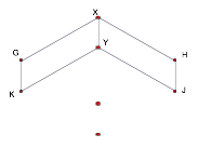
30) The complete the box by constructing the segments. Notice that as you change the width of the square to cut out or the length of the side of the box, the three-dimensional box changes accordingly. You can measure the sides of the box to show the relationship.
Task 2: Maximum Volume of a cylinder:
Click the GSP file for construction instructions.